What is a series circuit in simple terms? Understanding simple electrical principles is vital for anybody inquisitive about electronics. One essential idea is the series circuit. This article will explain what a series circuit is in simple phrases, providing clear knowledge for beginners. We may even talk about its traits, applications, and differences from parallel circuits.
Key Takeaways:
- Single Pathway: In a series circuit, there’s best one pathway for the current to glide. If the route is interrupted at any point, the entire circuit stops working.
- Current is the Same: The electric modern is the same at all points in the collection circuit. The present-day flows through one factor flows through all of the components.
- Voltage Splits: The total voltage across the circuit is the sum of the voltages throughout every aspect. Each element in a series circuit has a voltage drop proportional to its resistance.
- Resistance Adds Up: The overall resistance in a sequence circuit is the sum of the individual resistances. Adding greater components will increase the overall resistance.
- Dependence on Each Component: If one element in a chain circuit fails (e.g., a bulb burns out), the complete circuit stops operating due to the fact the course is broken.
- Applications: Series circuits are used in packages wherein the operation of the circuit is dependent on each issue, including in Christmas tree lighting or older-style string lights.
Introduction to Series Circuits
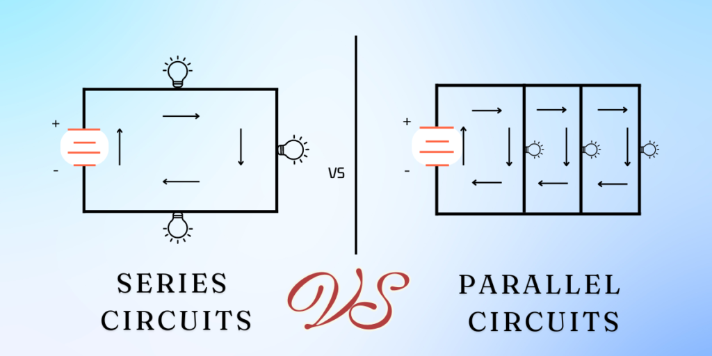
A collection circuit is one of the handiest forms of electrical circuits. In a chain circuit, all components are connected cease-to-cease, forming an unmarried course for the float of electric current. This method that the cutting-edge flows through everything one after the opposite. If the course is interrupted at any point, the whole circuit stops operating.
How Does a Series Circuit Work?
Basic Components of a Series Circuit
To apprehend what a series circuit is in easy phrases, it’s vital to understand its simple additives:
- Power Source: Provides the electricity needed to circulate electrons through the circuit (e.g., batteries).
- Conductors: Wires that join all additives and permit modern-day to float.
- Load: Any tool that uses the electric modern-day (e.g., light bulbs, resistors).
Current Flow in a Series Circuit
In a sequence circuit, the modern flows in one continuous direction. Since there’s handiest one direction, the modern is equal at any point in the circuit. If you have more than one mass (like light bulbs), the same modern passes via everyone. This function makes it easy to calculate the total resistance and modern-day in the circuit.
Voltage in a Series Circuit
The voltage in a sequence circuit is divided by some of the masses. Each load makes use of a portion of the entire voltage furnished by the energy source. This means that if you degree the voltage throughout every load and upload them up, it will same as the overall voltage from the strength supply.
Characteristics of a Series Circuit
Understanding what a series circuit is in easy phrases entails recognizing its key characteristics:
- Single Path: There is the most effective path for modern-day go-with-the-flow.
- Same Current: The current is identical through all components.
- Voltage Division: The general voltage is divided into a few of the hundreds.
- Dependence: If one thing fails, the complete circuit stops operating.
Calculating Values in a Series Circuit
Ohm’s Law in Series Circuits
Ohm’s Law is fundamental in understanding series circuits. It states that V=I×RV = I \times R, where VV is voltage, II is current, and RR is resistance. In a series circuit, you can use Ohm’s Law to calculate the total resistance, voltage drop across each component, and the total current.
Total Resistance in a Series Circuit
To find the total resistance in a series circuit, simply add the resistance values of each component: Rtotal=R1+R2+R3+…+RnR_{total} = R_1 + R_2 + R_3 + \ldots + R_n Where R1, R2, R3,…, RnR_1, R_2, R_3, \ldots, R_n are the resistances of individual components.
Voltage Drop Across Components
The voltage drop across each component in a series circuit can be calculated using Ohm’s Law: Vi=I×RiV_i = I \times R_i Where ViV_i is the voltage drop across component ii, II is the current, and RiR_i is the resistance of component ii.
Example Calculation
Let’s illustrate what a series circuit is in simple terms with an example. Suppose you have a series circuit with a 9V battery and three resistors of 2Ω, 3Ω, and 4Ω.
- Total Resistance: Rtotal=2Ω+3Ω+4Ω=9ΩR_{total} = 2\Omega + 3\Omega + 4\Omega = 9\Omega
- Current: Using Ohm’s Law, I=VRI = \frac{V}{R}: I=9V9Ω=1AI = \frac{9V}{9\Omega} = 1A
- Voltage Drop Across Each Resistor: V1=1A×2Ω=2VV_1 = 1A \times 2\Omega = 2V V2=1A×3Ω=3VV_2 = 1A \times 3\Omega = 3V V3=1A×4Ω=4VV_3 = 1A \times 4\Omega = 4V
Applications of Series Circuits
Household Applications
Series circuits are commonly determined in household devices. For instance, a few Christmas lights are stressed out in the collection. If one bulb burns out, the entire string of lights will exit due to the fact the circuit is broken.
Electronic Devices
In electronics, collection circuits are used in programs wherein the present-day wishes to stay regular across all components. For instance, in a string of LEDs, connecting them in a collection ensures they all get hold of the same modern-day, preventing any from burning out due to excess modern-day.
Safety Devices
Series circuits also are used in protection devices like fuses and circuit breakers. These components are designed to break the circuit if the present day exceeds a safe degree, protecting the rest of the device.
Series Circuits vs. Parallel Circuits
Differences Between Series and Parallel Circuits
To completely draw close to what a chain circuit is in easy terms, it’s helpful to examine it with a parallel circuit:
- Pathways: Series circuits have one course for contemporary drift; parallel circuits have multiple paths.
- Current: In a sequence circuit, the current is identical through all additives; in a parallel circuit, the cutting edge can range throughout unique branches.
- Voltage: Voltage is divided among hundreds in a series circuit; in a parallel circuit, the voltage across each branch is similar to the supply voltage.
- Dependence: In a chain circuit, if one thing fails, the entire circuit stops working; in a parallel circuit, different branches can still feature if one branch fails.
Example of Parallel Circuit
In a parallel circuit, a couple of resistors are linked such that every has its separate course to the energy source. This configuration allows gadgets to function independently of each other.
Common Misconceptions About Series Circuits
Misconception: Current is Divided
A common false impression is that the modern-day is split a number of the additives in a chain circuit. In reality, the contemporary is identical through all additives. It’s the voltage that is divided.
Misconception: Series Circuits are Always Better
While collection circuits have their blessings, they’re now not constantly the excellent choice. For instance, in case you need reliability and need the circuit to hold working even though one factor fails, a parallel circuit is more appropriate.
| Characteristic | Description |
|---|---|
| Current (I) | The same current flows through all components. |
| Voltage (V) | The total voltage is the sum of the voltages across each component. |
| Resistance (R) | The total resistance is the sum of the individual resistances of each component. |
| Failure Impact | If one component fails, the entire circuit is interrupted, and no current flows. |
| Connection Method | Components are connected end-to-end, forming a single path for current to flow. |
| Example Components | Resistors, capacitors, inductors, and batteries are connected in series. |
| Total Voltage Formula | Vtotal=V1+V2+V3+…+VnV_{total} = V_1 + V_2 + V_3 + … + V_n |
| Total Resistance Formula | Rtotal=R1+R2+R3+…+RnR_{total} = R_1 + R_2 + R_3 + … + R_n |
| Current Formula | Itotal=VtotalRtotalI_{total} = \frac{V_{total}}{R_{total}} |
Practical Tips for Working with Series Circuits
Ensuring Proper Connections
When constructing a sequence circuit, ensure all connections are stable. An unfastened connection can interrupt the circuit, causing it to stop working.
Calculating Correct Values
Always use Ohm’s Law to calculate the precise values for cutting-edge, voltage, and resistance. This ensures the additives work as meant and prevent damage.
Safety Precautions
When running with electrical circuits, constantly follow safety precautions. Ensure the strength source is grown to become off whilst assembling or enhancing the circuit to keep away from electric shocks.


