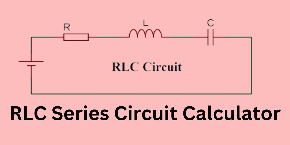
RLC Series Circuit Calculator, When coping with electrical circuits, information on the intricacies of RLC collection circuits is vital.
An RLC series circuit consists of a resistor (R), an inductor (L), and a capacitor (C) related in a chain configuration.
These circuits are widely utilized in various packages, from radio receivers to power substances. To simplify the evaluation and layout of these circuits, an RLC series circuit calculator can be a useful tool.
In this article, we will discover what you want to recognize about RLC series circuit calculators, the way to use them, and why they’re essential for absolutely everyone operating with electric circuits.
Key Takeaways:
- Fundamental Understanding: RLC series circuit calculators help comprehend the behavior and characteristics of RLC circuits, aiding both students and professionals in grasping fundamental electrical principles.
- Analysis and Design: With these calculators, engineers can analyze various parameters of RLC circuits such as impedance, current, voltage, and resonance frequency. They can also use them to design circuits tailored to specific requirements.
- Time-saving: Calculating complex RLC circuit parameters manually can be time-consuming and prone to errors. RLC series circuit calculators automate these calculations, saving valuable time and ensuring accuracy.
- Educational Tool: These calculators serve as educational tools, facilitating learning and experimentation with RLC circuits. They allow students to explore different scenarios and observe the effects of changing component values.
- Practical Application: Beyond educational purposes, RLC series circuit calculators find practical applications in various industries such as telecommunications, power electronics, and signal processing, where precise circuit analysis is essential for design and troubleshooting.
Understanding RLC Series Circuits
What is an RLC Series Circuit?
An RLC collection circuit is a kind of electrical circuit wherein a resistor, an inductor, and a capacitor are connected quit-to-lead to a single path for the modern to go with the flow. This configuration combines the resistive, inductive, and capacitive residences, which have an effect on the circuit’s normal impedance and behavior under distinctive frequencies.
Components of an RLC Series Circuit
- Resistor (R): It resists the glide of electrical present day, causing a voltage drop. It is measured in ohms (Ω).
- Inductor (L): It opposes adjustments in modern and shop energy in a magnetic area. It is measured in Henry (H).
- Capacitor (C): It stores electricity in an electric field and opposes modifications in voltage. It is measured in farads (F).
How an RLC Series Circuit Calculator Works
An RLC series circuit calculator is designed to help you compute diverse parameters of an RLC circuit, together with general impedance, resonant frequency, segment attitude, and greater. These calculators generally require you to input values for resistance (R), inductance (L), and capacitance (C).
Key Parameters Calculated
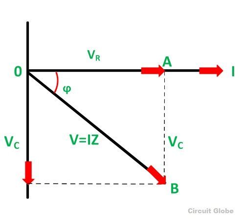
- Total Impedance (Z): The overall competition to the drift of alternating modern-day (AC), combining resistance, inductive reactance, and capacitive reactance.
- Resonant Frequency (f₀): The frequency at which the inductive reactance equals the capacitive reactance, inflicting the circuit to resonate.
- Damping Factor: Indicates how oscillations in a circuit decay over time.
- Quality Factor (Q): Measures the sharpness of the resonance peak.
Using an RLC Series Circuit Calculator
To use an RLC series circuit calculator, follow the steps:
- Input Values: Enter the resistance (R), inductance (L), and capacitance (C) values into the calculator.
- Calculate: Click the calculate button to achieve consequences.
- Interpret Results: Review the calculated parameters to understand the behavior of your RLC circuit.
Example Calculation
Consider an RLC series circuit with:
- Resistor: 10 Ω
- Inductor: 0.05 H
- Capacitor: a hundred μF
By inputting these values into an RLC series circuit calculator, you can determine the total impedance, resonant frequency, and different key parameters.
Importance of RLC Series Circuit Calculators
Simplifying Complex Calculations
RLC circuits involve complex mathematical formulas. An RLC series circuit calculator simplifies those calculations, saving time and lowering the capability for mistakes.
Enhancing Circuit Design
Designing efficient circuits requires unique calculations. These calculators assist engineers and hobbyists in exceptional-singing their circuits for the most reliable overall performance.
Educational Tool
For college students and educators, RLC collection circuit calculators serve as outstanding instructional gear, helping with the understanding of circuit behavior and traits.
Key Features to Look for in an RLC Series Circuit Calculator
User-Friendly Interface
A precise RLC series circuit calculator needs to have a straightforward, intuitive interface that allows for easy input of values and brief get-right of entry to effects.
Comprehensive Calculations
Ensure the calculator offers a huge range of calculations, along with impedance, resonant frequency, section attitude, and more.
Accuracy
Accurate outcomes are critical for effective circuit design and analysis. Look for calculators that might be acknowledged for their precision.
Common Applications of RLC Series Circuits
RLC series circuits are determined in several applications, along with:
- Radio Receivers: Used for tuning to unique frequencies.
- Oscillators: Essential in producing signals of unique frequencies.
- Filters: Used to allow or block certain frequency ranges.
- Power Supplies: Help in smoothing out fluctuations in voltage and contemporary.
Table for RLC Series Circuit Calculator
| Parameter | Description |
|---|---|
| Impedance (Z) | Total opposition to current flow in the circuit |
| Resonance Frequency | The frequency at which the circuit resonates |
| Current (I) | Flow of electric charge in the circuit |
| Voltage (V) | Potential differences across the circuit |
| Power (P) | Rate of energy transfer in the circuit |
FAQs about the RLC Series Circuit Calculator
What is the resonant frequency in an RLC series circuit?
The resonant frequency (f₀) is the frequency at which the inductive reactance (XL) equals the capacitive reactance (XC). It can be calculated using the formula:
𝑓0=12𝜋𝐿𝐶
How do you calculate impedance in an RLC series circuit?
The total impedance (Z) in an RLC series circuit is calculated using the formula:
𝑍=𝑅2+(𝑋𝐿−𝑋𝐶)2
where 𝑋𝐿=2𝜋𝑓𝐿 and 𝑋𝐶=12𝜋𝑓𝐶.
Why is the quality calculation (Q) important?
The quality calculation (Q) shows the sharpness of the reverberation crest. A higher Q implies a smaller and more honed top, which is critical in applications like channels and oscillators.
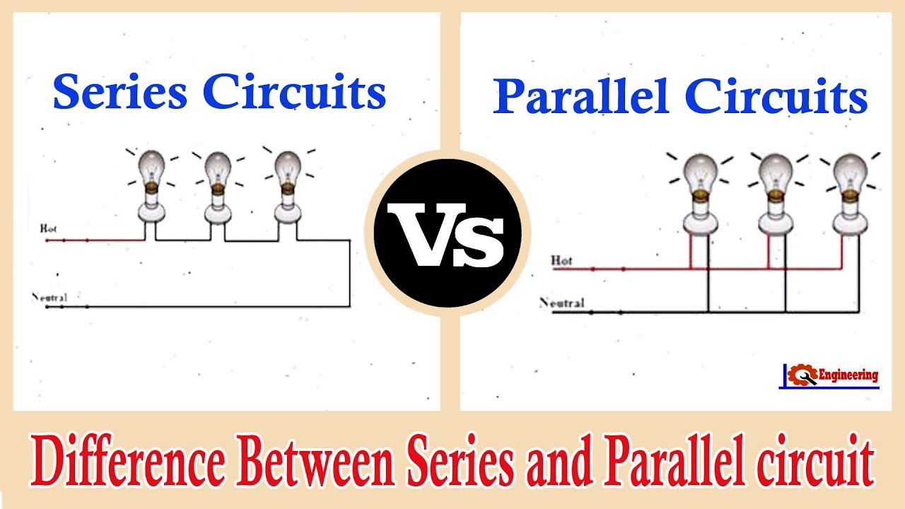
Can I utilize an RLC arrangement circuit calculator for parallel circuits?
No, an RLC arrangement circuit calculator is particularly planned for arrangement circuits. Parallel circuits require distinctive calculations and hence a distinctive sort of calculator.
What happens at reverberation in an RLC arrangement circuit?
At reverberation, the inductive reactance and capacitive reactance cancel each other out, coming about in the circuit’s impedance being simply resistive. This leads to the greatest current flow.
Conclusion
An RLC arrangement circuit calculator is a fundamental device for anybody working with electrical circuits. It streamlines complex calculations, helps in effective circuit plans, and serves as an instructive asset. By understanding how to utilize these calculators and the significance of the key parameters they compute, you can optimize your RLC arrangement circuits for a wide run of applications.
Whether you’re a designer, an understudy, or a specialist, the utilization of an RLC arrangement circuit calculator will upgrade your capacity to plan and analyze electrical circuits viably. Grasp this effective device to make your circuit plan preparation more productive and exact.