 Skip to content
 Hello, how are you? I hope you are happy in life, welcome to our blogs! I hope you like this article of mine. I try to share with you about parallel circuits in every article.
I always try to share with you the knowledge that no blogger has given you before today. Let’s move on and get complete information on how to find resistance in a parallel circuit.
Introduction
Parallel circuits are an essential part of electric engineering and electronics. I find it fascinating how these circuits offer a couple of pathways for cutting-edge to go with the flow.
When components are connected in parallel, they proportion the equal voltage source, which allows every element to paint independently.
This independence is crucial because if one aspect fails, the others can keep functioning. In this newsletter, I’ll discover how to calculate general resistance in parallel circuits, speak not unusual errors, and spotlight actual global programs.
The Formula for Calculating Total Resistance in Parallel Circuits
The Formula for Calculating Total Resistance in Parallel Circuits
To find the total resistance (RTR_T) in a parallel circuit, I use the reciprocal formula:
1RT=1R1+1R2+1R3+…+1Rn\frac{1}{R_T} = \frac{1}{R_1} + \frac{1}{R_2} + \frac{1}{R_3} + \ldots + \frac{1}{R_n}
If I’m only working with two resistors, I can simplify it to:
RT=R1×R2R1+R2R_T = \frac{R_1 \times R_2}{R_1 + R_2}
This formula clearly shows that the total resistance in a parallel circuit is always less than the smallest resistor in the group.
Step-by using-Step Guide to Finding Resistance in Parallel Circuits
When I want to locate overall resistance, the first step is to pick out all of the resistors related in parallel. After listing their values, I observed the correct formulation for parallel resistance.
If I’m handling simply two resistors, the simplified formulation makes calculations trustworthy. I ensure to perform the arithmetic carefully and double-take a look at my consequences for accuracy.
Common Mistakes When Calculating Resistance in Parallel Circuits
I’ve observed a few common mistakes that could occur when calculating resistance in parallel circuits. One common mistake is forgetting the reciprocal nature of the formula, which can result in incorrect results.
It’s additionally smooth to confuse the formulation for series and parallel circuits, which can bring about giant mistakes. Additionally, rounding errors, specifically with decimals, can complicate matters, so I usually stay meticulous in my calculations.
Real-World Applications of Parallel Circuit Resistance Calculation
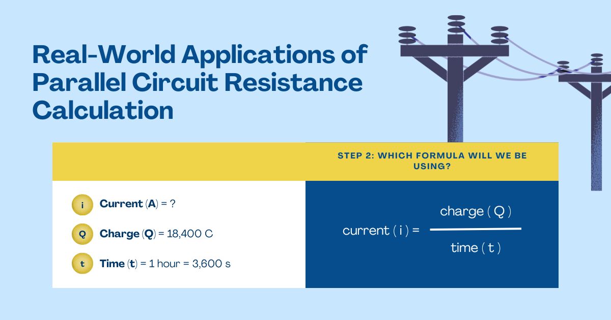
I discovered that parallel circuits have many practical programs. For instance, in residential electrical systems, shops, and lights are frequently wired in parallel.
This allows them to function independently, which is important for normal use. In electronics, circuit boards utilize parallel configurations to distribute power efficiently.
Similarly, in automotive electric systems, parallel circuits help energy-diverse gadgets, making sure the entirety continues to paintings even if one factor fails.
Visualizing Resistance: Diagrams and Examples of Parallel Circuits
To visualize how parallel circuits paint, I imagine a diagram wherein more than one resistor—like R1, R2, and R3—is connected throughout a voltage source.
Each resistor branches from the main circuit, showcasing more than one pathway for contemporary.
In this setup, the voltage throughout every resistor remains equal, even as the whole cutting edge is the sum of the currents flowing through each department.
Comparing Series and Parallel Circuit Resistances: Key Differences
When I compare collection and parallel circuits, one key difference stands proud: current behavior. In collection circuits, the modern is identical in every aspect, while in parallel circuits, the whole cutting edge divides many of the special branches.
Additionally, the voltage is steady throughout components in parallel circuits, however it’s miles divided in collection circuits. The methods for calculating total resistance additionally fluctuate notably between those configurations.
Troubleshooting Tips for Resistance Measurement in Parallel Circuits
When I measure resistance in parallel circuits, I make sure to use my multimeter successfully. I ensure it’s set to the proper resistance size mode.
It’s crucial to measure resistance with the circuit powered off to keep away from the multimeter. I also test that every connection is stable, as loose connections can lead to inaccurate readings.
Exploring the Impact of Resistance on Circuit Performance
Resistance has a sizable impact on the circuit’s overall performance. In parallel circuits, a lower total resistance permits for a better overall contemporary, that may decorate average capability.
However, if the contemporary becomes excessive, it can lead to overheating or component failure. This highlights why correctly calculating resistance is vital whilst designing circuits.
FAQs
Why is the total resistance in a parallel circuit always less than the smallest resistor?
The total resistance is always less because adding more pathways for current decreases the overall opposition to flow. This allows more current to pass through the circuit.
What happens if one resistor in a parallel circuit fails?
If one resistor fails (opens), the other resistors will continue to operate, allowing the circuit to function normally. This is a key advantage of parallel circuits.
Can I have a circuit with all resistors of the same value in parallel?
Yes, you can. If all resistors have the same value RR and there are no resistors, the total resistance can be calculated as:
RT=RnR_T = \frac{R}{n}
How do I measure the total resistance in a parallel circuit with a multimeter?
To measure total resistance, first, ensure the circuit is powered off. Set the multimeter to the resistance measurement mode, and connect the probes across the terminals of the circuit to get the total resistance reading.
What if I only have two resistors? Is the calculation simpler?
Yes, when only two resistors are in parallel, you can use the simplified formula:
RT=R1×R2R1+R2R_T = \frac{R_1 \times R_2}{R_1 + R_2}
This makes calculations much quicker.
Can I combine series and parallel resistances?
Yes, you can combine them in complex circuits. Calculate the total resistance for series parts and then for parallel parts separately, using the appropriate formulas for each section.
How does resistance affect current in a parallel circuit?
The lower total resistance in a parallel circuit results in a higher total current, assuming the voltage remains constant.
This means each pathway can carry more current, which can lead to better performance but requires careful consideration to avoid overheating.
Conclusion
In the end, knowledge of parallel circuits and their resistance calculations is crucial for absolutely everyone inquisitive about electronics or electric engineering.
I’ve determined that those ideas are not handiest foundational for circuit layout but additionally essential for ensuring reliability and efficiency in real-world programs.
With practice and careful attention to detail, the standards surrounding parallel resistance grow to be greater intuitive, assisting in powerful troubleshooting and design.
