A phasor diagram is a graphical representation used to illustrate the relationship between different voltages and currents in an AC circuit, particularly useful in analyzing the behavior of an RC series circuit. The purpose of the phasor diagram is to provide a clear understanding of the phase difference between the applied voltage, the current, and the voltage across individual components (resistor and capacitor) in the circuit.
What is a Phasor Diagram of an RC Series Circuit?
In an RC series circuit, a resistor (R) and a capacitor (C) are connected in series to an alternating current (AC) supply. The phasor diagram represents the voltages and currents in the circuit as rotating vectors, or “phasors,” to show their magnitude and phase relationships at any given point in time.
Components of the Phasor Diagram
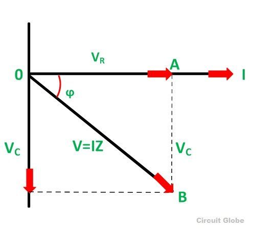
- Voltage across the Resistor (V_R): The voltage drop across the resistor is in phase with the current. In the phasor diagram, this is shown as a vector aligned along the horizontal axis.
- Voltage across the Capacitor (V_C): The voltage across the capacitor lags the current by 90 degrees. In the phasor diagram, this is represented as a vector pointing downward or at a -90° angle relative to the current.
- Total Voltage (V): The total supply voltage in the circuit is the vector sum of the individual voltages across the resistor and capacitor. It is typically shown as a diagonal phasor resulting from the combination of V_R and V_C.
- Current (I): The current in an RC series circuit is a common reference, and all voltages are shown relative to this current. The current phasor is often drawn along the horizontal axis, as it represents the phase reference.
Phase Relationships
- The current (I) leads the voltage across the capacitor (V_C) by 90 degrees.
- The current is in phase with the voltage across the resistor (V_R).
- The total supply voltage (V) lags behind the current, with the phase difference depending on the frequency of the AC supply.
As the frequency of the input AC voltage increases, the capacitive reactance (X_C) decreases, leading to a smaller phase shift between the total voltage and the current. Conversely, at lower frequencies, the capacitive reactance increases, and the total voltage lags the current more significantly.
Impedance in Phasor Diagram
The impedance (Z) in an RC series circuit is the total opposition to the AC current, and it is a combination of both the resistance (R) and the reactance of the capacitor (X_C). The impedance vector in the phasor diagram is represented as the resultant of R and X_C, forming an angle (θ) with the horizontal axis, where:
θ=arctan(XCR)\theta = \arctan\left(\frac{X_C}{R}\right)
This angle indicates the phase difference between the current and the total voltage. The impedance magnitude is given by:
Z=R2+XC2Z = \sqrt{R^2 + X_C^2}
Conclusion
The phasor diagram of an RC series circuit is an essential tool in AC circuit analysis. It visually represents the relationships between the voltages, current, and impedance, making it easier to understand how each component behaves with respect to each other. By examining the phase differences and magnitudes in the phasor diagram, engineers and students can gain valuable insights into the behavior of the circuit at various frequencies.


