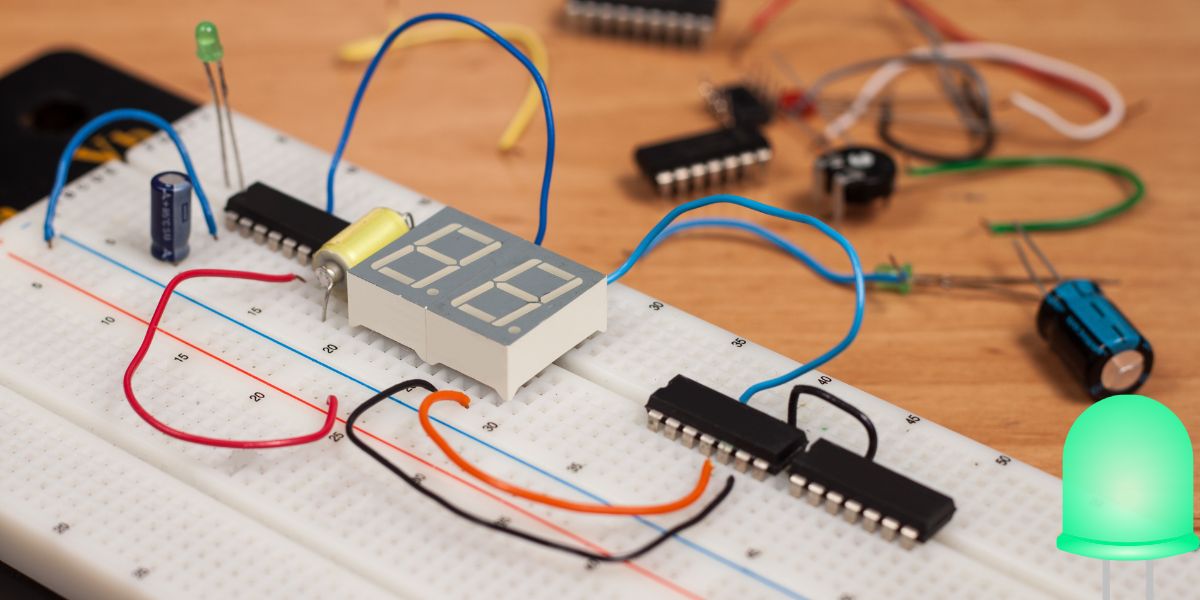
Parallel Circuit Breadboard LED, In the realm of electronics, breadboards serve as quintessential tools for prototyping circuits before their implementation.
Among the essential circuit configurations is the parallel circuit, which gives several packages, mainly in light structures.
In this guide, we delve into the intricacies of building, wiring, and troubleshooting a parallel circuit for LEDs on a breadboard.
key takeaway
- Place LEDs on the Breadboard: Screw each LED into the breadboard. Check whether the positive and negative terminal is in the correct position as anode (positive leg) and cathode (negative leg) respectively.
- Connect the Resistors: Connect a resistor in series with an LED. It reduces the amount of current passing through these LEDs to a level that would not cause the NOOBS to break. Bend the resistor’s one end in a loop and insert it across the LED’s anode and the positive rail of the breadboard.
- Wire the LEDs in Parallel: Circuit all the anodes of all the LEDs to a single row on the breadboard. All the cathodes of the LEDs should be connected to another common row of the LED board.
- Power the Circuit: Screw the wires connecting the positive terminal of the power source in the positive rail and the negative terminal of the power source in the negative rail of the breadboard.
- Consistency: Check and double-check all the connections and their consistency. Unreliable operation is caused by loose wires.
- Resistor Values: This will require Ohm’s Law to fuel the right resistor values for your LEDs depending on the forward voltage and the amount of current you would wish it to pass.
- Power Source Matching: Make sure the voltage of the power supply you use is compatible with the voltage rating of the LEDs and the calculated resistors. The brightness can also be affected and too high a voltage can even harm the LEDs.
- Place LEDs on the Breadboard: Screw each LED into the breadboard. Check whether the positive and negative terminal is in the correct position as anode (positive leg) and cathode (negative leg) respectively.
- Connect the Resistors: Connect a resistor in series with an LED. It reduces the amount of current passing through these LEDs to a level that would not cause the NOOBS to break. Bend the resistor’s one end in a loop and insert it across the LED’s anode and the positive rail of the breadboard.
- Wire the LEDs in Parallel: Circuit all the anodes of all the LEDs to a single row on the breadboard. All the cathodes of the LEDs should be connected to another common row of the LED board.
- Power the Circuit: Screw the wires connecting the positive terminal of the power source in the positive rail and the negative terminal of the power source in the negative rail of the breadboard.
Understanding Parallel Circuits
What is a Parallel Circuit?
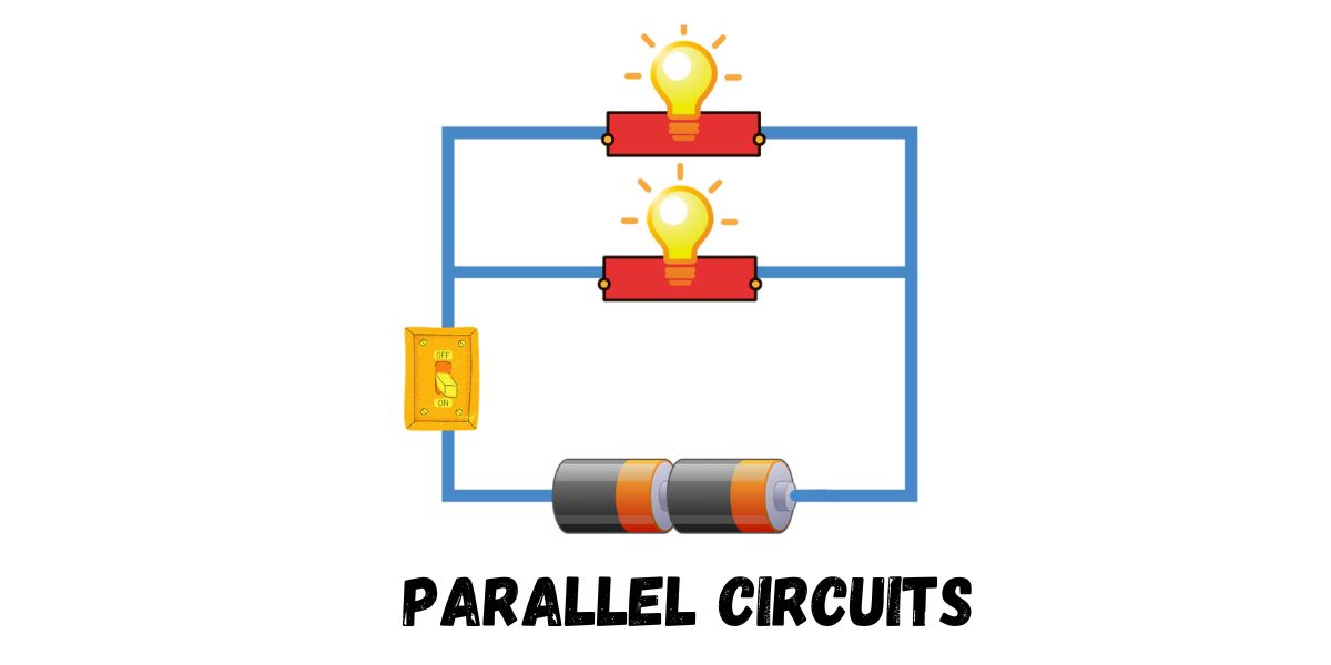
A parallel circuit is a configuration where components are connected in such a way that the current has a couple of paths to flow. Each thing in a parallel circuit is connected throughout the same voltage supply.
Advantages of Parallel Circuits
Parallel circuits offer numerous advantages, including:
- Independent Operation: Components in a parallel circuit function independently, making sure that if one aspect fails, others continue to feature.
- Even Voltage Distribution: Voltage remains regular across each thing in a parallel circuit, making sure of uniform operation.
- Easy Troubleshooting: Identifying and rectifying faults in parallel circuits is quite trustworthy due to the impartial operation of additives.
Building a Parallel Circuit with LEDs on a Breadboard
Materials Required
Before proceeding, acquire the following substances:
1. LED bulbs
2. Breadboard
3. Resistors (if wanted)
4. Jumper wires
5. Power supply (battery or DC adapter)
Step-by means of-Step Guide
Follow the steps to build a parallel circuit with LEDs on a breadboard:
- Prepare the Breadboard: Insert the LED bulbs into the breadboard, ensuring that the anode (longer leg) of each LED connects to the fantastic rail and the cathode (shorter leg) connects to the terrible rail.
- Connect the LEDs in Parallel: Use jumper wires to attach the tremendous rail to the anode of every LED and the terrible rail to the cathode of every LED.
- Add a Resistor (if important): Depending on the specifications of your LEDs and strength source, you could need to include a resistor in the collection with every LED to restrict the contemporary waft and save you harm. Calculate the appropriate resistor value for the usage of Ohm’s Law.
- Power the Circuit: Connect the electricity delivered to the breadboard, ensuring that the polarity is correct.
- Test the Circuit: Apply power to the circuit and examine the illumination of the LEDs. Ensure that every LED is functioning successfully.
Wiring Considerations and Troubleshooting
Wiring Considerations
When wiring a parallel circuit with LEDs on a breadboard, recollect the following:
- Polarity: Ensure that the polarity of the LEDs is accurate to save you opposite biasing, which could damage the components.
- Current Limiting: Use resistors to limit the current flowing via the LEDs to save you from overheating and premature failure.
- Wire Gauge: Choose appropriate gauge jumper wires to handle the present-day necessities of the circuit without voltage drops or overheating.
Troubleshooting Tips
If you come across troubles together with your parallel circuit, bear in mind the subsequent troubleshooting pointers:
- Check Polarity: Verify that the LEDs are connected with the best polarity.
- Inspect Connections: Ensure that every connection on the breadboard is secure and unfastened from unfastened wires or additives.
- Test Components: Use a multimeter to check the voltage and continuity of character additives to identify any defective elements.
FAQs about Parallel Circuit Breadboard LED
Can I mix different shade LEDs in a parallel circuit?
Yes, you may blend distinct color LEDs in a parallel circuit with no problems. Each LED operates independently, so the color of 1 LED no longer affects the others.
Do I need a resistor for each LED in a parallel circuit?
It relies upon the voltage rating of your LEDs and the electricity supply. In some cases, an unmarried resistor related in collection with all LEDs can also suffice, at the same time as in others, individual resistors for each LED are vital to make certain uniform brightness.
What happens if one LED fails in a parallel circuit?
If one LED fails in a parallel circuit, the others will preserve to operate unaffected. This is one of the benefits of parallel circuits, as they provide redundancy and impartial operation.
Conclusion
In the end, constructing a parallel circuit with LEDs on a breadboard is a fundamental ability for electronics enthusiasts and specialists alike. By knowledge of the standards of parallel circuits and following the stairs mentioned in this guide, you could create green lighting fixtures and structures and troubleshoot any troubles that can arise. Remember to take note of wiring considerations and use suitable components to ensure the achievement of your circuit initiatives. Happy experimenting!


